|
Nearly everyone associates aftermarket rocker arms with high performance engines, however few people actually understand them. Often these rocker arms are purchased in an attempt to increase engine performance, but do not always achieve the intended results. Understanding how, when and why aftermarket rocker arms are beneficial to your engine will help you avoid dissapointing results and costly mistakes. The following article discusses the fundamental airflow needs of an engine and how rocker arms contribute to the ability of meeting those needs.
A Rocker arm is a lever through which the action of the camshaft is transferred to the valve itself and the ratio of movement generated at the valve, to the amount of camshaft lift, is called the rocker arm ratio. Stock MGB rocker arms are quoted as being a 1.426:1 ratio. This means the lift obtained at the cam is multiplied by 1.426 to obtain the actual amount of valve opening. To understand why this multiplication factor is important, let's consider the following.
As a piston moves up and down inside the cylinder of an engine, it will generate a corresponding demand for airflow in or out, relative to its velocity and direction. Therefore, piston movement is the root cause of airflow within the engine and when the piston speed is high, the airflow demand is as well. When looking at the accompanying graph, we can see that piston velocity is not constant throughout the stroke, but peaks some 75° after top dead center. This shows how airflow demand is greatest at or around this point.
In viewing the second graph (which represents the airflow test results from one of our "Fast Road" MGB cylinder heads), it can be clearly seen how increases in valve lift equate to increases in airflow delivery. These graphs suggest that achieving maximum valve opening during times when the piston is demanding the greatest airflow, will allow the greatest volumetric efficiecy and thus power.
By increasing ratio over that of factory stock rockers, aftermarket rocker arms can generate even greater amounts of valve lift during the valve opening cycle. Simply put, this increased lift allows more airflow into the engine on the inlet side and more exhaust flow out of the engine on the exhaust side. Choosing and properly installing the best aftermarket rocker arm for your situation however, may not be so simplistic.
One of the pitfalls of any roller tip rocker arm, is that none can deliver a constant ratio of movement over the full cycle of valve lift. Because rocker arms multiply linear motion through two different arcs of rotation, the angles of the rocker arm to the axis of the linear moving parts (valve and pushrod) have a direct effect on the amount of motion transferred across it. When a rocker arm is first installed (with the valve fully closed), this angular relationship is referred to as the "installed geometry".
Installed geometry can be thought of as the "starting point" from which the rocker arm will rotate as the valve opens. A good installed geometry will start the rocker arm off at angles beneficial to the engine's performance, while improper installed geometry will not. Three main categories of installed geometry are likely to be obtained, "worst," "better," and "best" as follows.
The worst installed geometry increases valve opening at low piston speeds and reduces valve opening at high piston speeds. Having a rocker arm magnify movement during times when the piston is moving very slowly (or often even the wrong way) results in increased charge reversion and only increases what is known as the overlap area of valve opening. Additionally, excessive rocker arm ratio at low valve lifts causes the valve to literally jerk off its seat and then slam closed again as it returns. A significant decrease in valve and seat life, as well as poor over all performance are the results.
At the other end of the spectrum is an installed geometry which results in low ratios at the opening and closing points, but high ratios near maximum valve opening. This situation is safer, because it results in smoother operation near the valve seat (reducing the jerking effects noted earlier). Unfortunately the greatest multiplication factor occurs only at peak valve lift when ideally, peak ratio would occur within the 1/2 to 2/3 lift area.
To achieve the best installed geometry, the rocker arm must be set so the center of the adjuster ball, rocker pivot and roller tip axis are all in perfect alignment. When this situation is met, a straight line (called the pivot axis line) can be drawn through these pivot points as seen in the photos at right. Failure to do this results in a non-linear rate of rocker arm motion, often to the detriment of engine performance.
The rocker shaft height must be set (via shims placed under the pedestals) to allow the rocker arm's pivot axis line to effect a 90° angle to the valve stem at the 1/2 to 2/3 lift point. If the actual ratio of the rocker arm is known, this point can be figured by multiplying 1/2 to 2/3 the camshaft lobe lift by the actual rocker arm ratio. The rocker pedestals may then be shimmed to achieve a rocker arm position 90° to the valve stem at that point.
Finally, the correct length pushrod must be obtained. Never attempt to compensate for a pushrod of improper length with the adjusters of the rocker arm! The companies listed in the links section are good sources for custom made, high quality pushrods, who will more than gladly make you a set to any length needed. The adjusters on rocker arms are for setting valve lash only and should never be used to compensate for an incorrect pushrod length, or very poor rocker arm geometry will result.
For more information pertaining directly to Harland Sharp rocker arms, click Here.
For more information pertaining directly to Titan rocker arms, click Here.
Article Links:
Advanced Performance Technology (Rocker arms, Shims and Pushrods)
Basil Adams (Shims and Pushrods)
Manton (pushrods)
Smith Brothers (pushrods)
Harland Sharp (rocker arms)
Titan Motorsport (rocker arm assemblies)
Fab-Tek (rocker arm conversions)
|
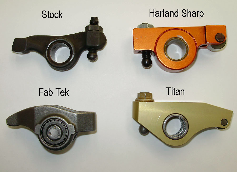
While some popular styles have roller tips, fulcurms, or both, the overall ratio and geometry of the rocker arm is actually most important. "Rollerized" features will likely show no measurable gain in and of themselves.
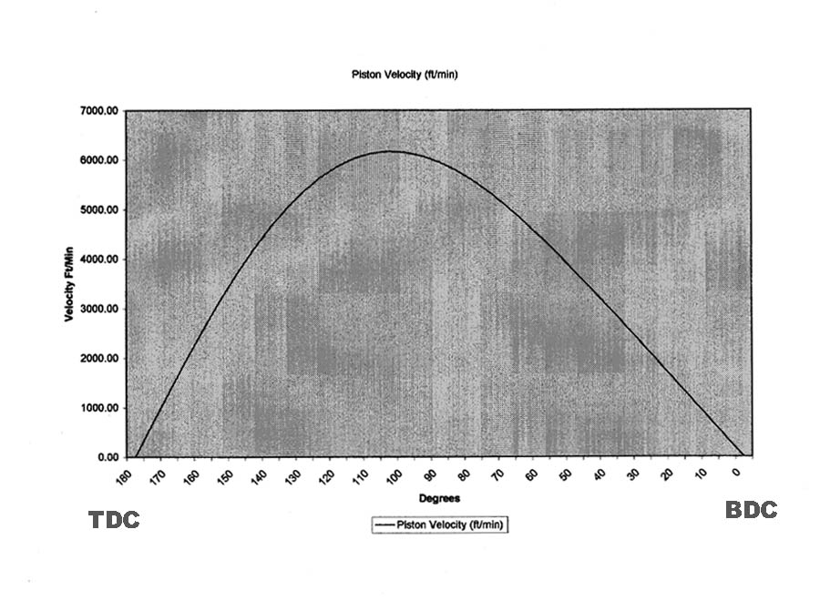
Piston speed calculated over 180 crankshaft degrees at 6,500RPM is seen above, with maximum velocity occurring 75 degrees after top dead center. (see text)
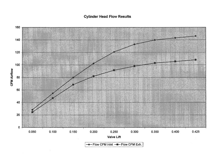
Shown are typical flow results from a modified MGB cylinder head. (see text)
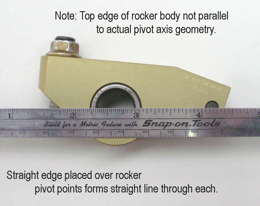
For best results, the rocker arm should exibit a "straight line" relationship between all points of rotation (called the "pivot axis line").
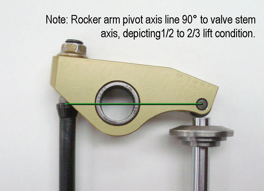
At the 1/2 to 2/3 lift point, a roller rocker's pivot axis line should be 90° to the vertical axis of the valve stem and pushrod.
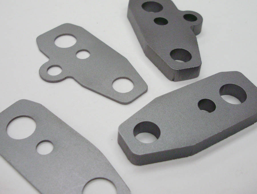
Rocker pedestal shims make rocker shaft height adjustments easy (suppliers listed at left).
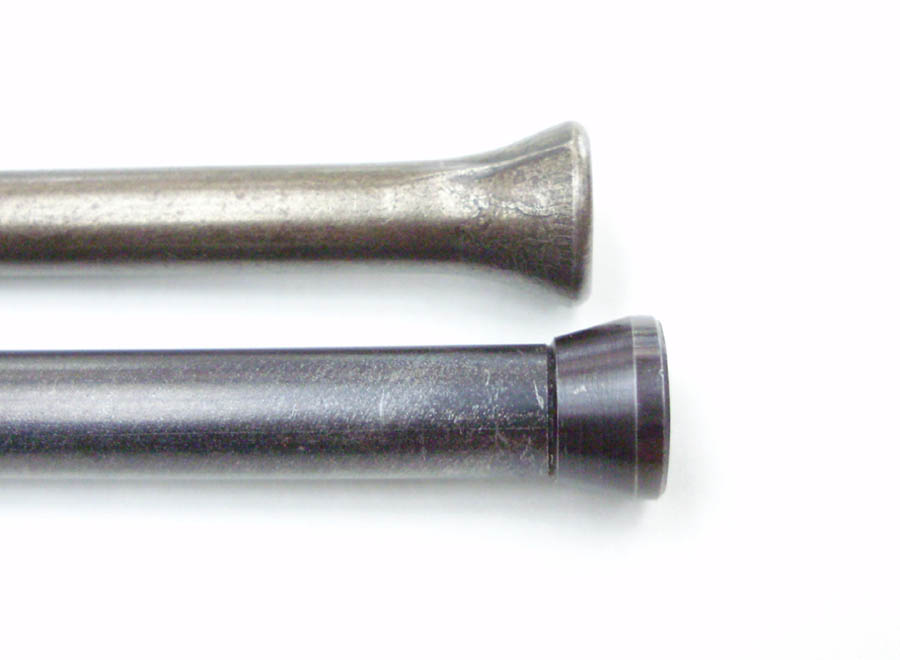
Not only are aftermarket pushrods stiffer, stronger and more durable, but they can also be made to any length needed.
|