|
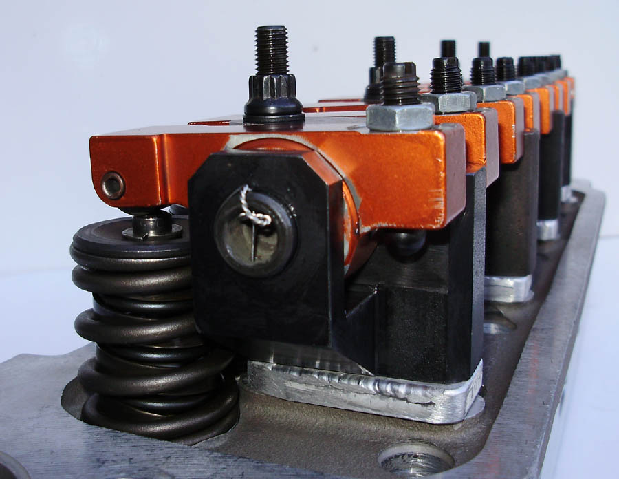
The lure of increased performance with relatively low purchase price has resulted in Harland Sharp rocker arms becoming a popular upgrade for many MGB enthusiasts. Although these rocker arms are advertised as a direct replacement part, some serious attention to detail is necessary if problems such as pushrod clearance and overall lack of performance are to be avoided. If you haven't already read The In's and Out's of Aftermarket Rocker Arms, doing so first will help you attain a better understanding of the theory behind the information presented below.
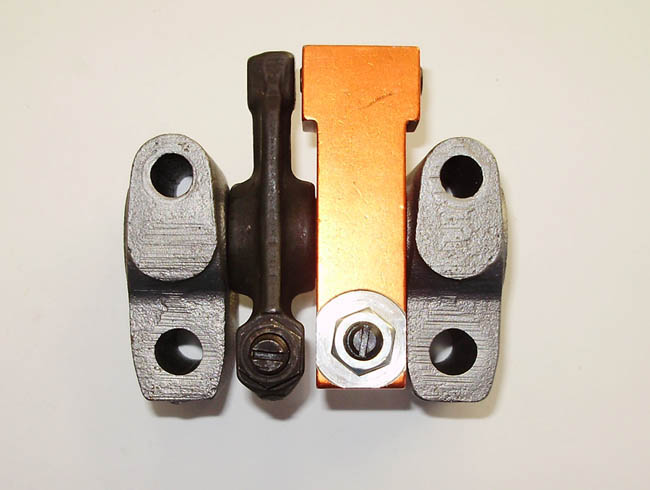
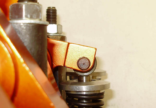
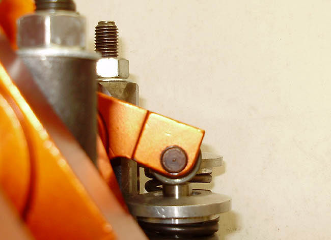
All the problems encountered when converting to Harland Sharp rocker arms can be attributed to the fact the original MGB rocker assembly was designed around a wiper pad style rocker arm, rather than a roller tip style rocker arm. This difference results in the original rocker shaft height being too low for the new roller tipped rocker arm design. In essence, you are making a modification to the design of the engine by installing these rocker arms and how well you do it, determines how well the engine performs when you are through.
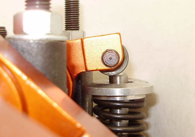
The first most important aspect to consider is how proper rocker shaft height is affected by the addition of a roller tip rocker arm. Wiper style rocker arms use the contact point of the wiper pad and valve tip as a pivot point, but roller tip rocker arms use the roller axle as their pivot point. This change in pivot location constitutes a need to raise the rocker shaft by a like amount if proper installed geometry is to be maintained.
Standard Harland Sharp rocker arms have an exceptionally large .3025" radius (.605" diameter) roller tip, while the British Automotive Spec. version has a smaller .2725" radius (.545" diameter) roller tip. Either set needs an increase in rocker shaft height however, with the standard version needing the greatest increase. If adding .300" worth of shim under the rocker pedestals were all that was necessary, life would be easy indeed. Unfortunately, camshaft lift also has a direct effect on proper rocker shaft height and cannot be ignored.
Since we'd like the rocker arm pivot axis line to affect a 90° angle to the valve stem at the 1/2 to 2/3 lift point, we start by multiplying 1/2 to 2/3 cam lift by our known rocker arm ratio. Proper rocker shaft height is then calculated by adding the roller radius to the valve tip height and subtracting the amount of valve lift figured previously. The formula is thus:
Rocker Shaft Centerline Height = (Valve Tip Height + Roller Radius) - (1/2 to 2/3 actual valve lift)
Just how critical is rocker shaft height for proper performance? In our testing, the installation of the 1.5:1 rocker arms with an uncorrected rocker shaft height resulted in a meager 1.44:1 peak ratio. Since the stock ratio is 1.426:1, these results show why many users of the Harland Sharp 1.5:1 sets cannot determine any performance increase once the conversion has been completed. In these cases, it's not the rocker arm itself that is to blame, but rather a simple lack of understanding on the part of the installer.
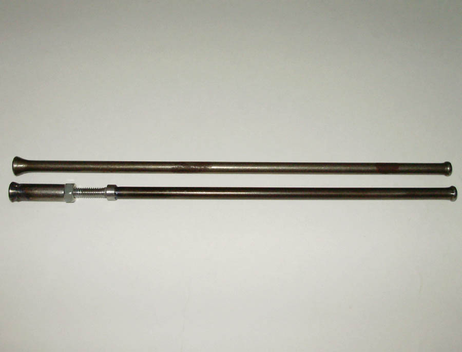
Shimming the rocker pedestals for correct shaft height is the first step toward achieving full delivered ratio, but pushrod length is equally as important. With the rocker shaft at the correct height, standard length pushrods will be too short. When rocker arm adjusters are used to compensate for pushrods that are too short, big changes to the delivered rocker arm ratio results. In our testing, the 1.5:1 rocker arm set achieved less than 1.42:1 maximum ratio with the adjusters extended to meet stock length pushrods.
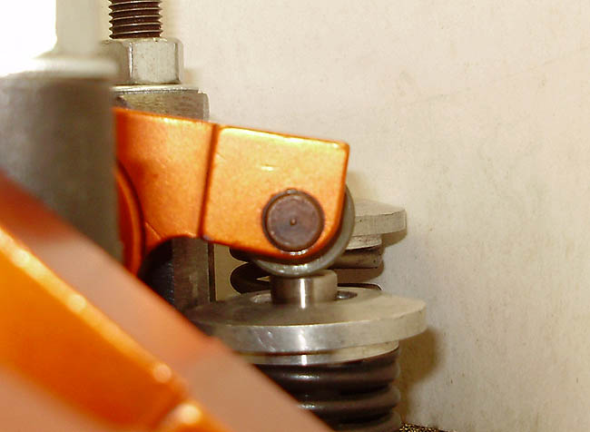
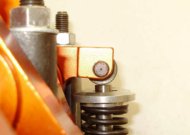
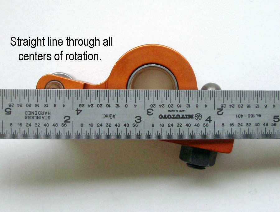
It is therefore important to set the rocker arm adjusters correctly before determining proper pushrod length. A straight line (called the pivot axis line) must be capable of being drawn through all the pivot points of the rocker arm. When this condition is met, the right length pushrod can be found using an adjustable length checking pushrod.
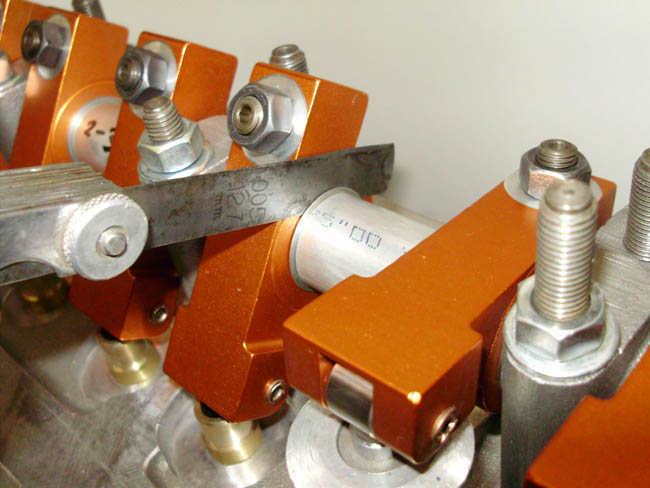
Checking pushrods can be lengthened or shortened as necessary to achieve the correct working length. The adjustable checking pushrod is set to its shortest length on installation and then extended until proper valve lash is obtained. Once the correct length is found, a full set of pushrods can be purchased. The suppliers listed below offer kits and pushrods to any length or size needed.
Example Math:
Correct rocker shaft centerline height for a .256" lobe cam and standard 1.5:1 ratio .605" diameter roller tip Harland Sharp rocker arms would be calculated as follows:
Example height of valve tip above rocker pedestal base in cylinder head = 1.625" (will be different for every cylinder head)
Roller tip radius = .3025"
One half net valve lift = (.256" / 2) = .128" × 1.5 = .192"
Therefore:
(1.625" + .3025") = 1.9275"
1.9275" - .192" = 1.7355"
1.7355" is the corrected rocker shaft centerline height above the pedestal base in the cylinder head.
Since the original rocker shaft centerline height = 1.4225"
1.7355" - 1.4225" = .313" rocker pedestal shims required.
Article Links:
Advanced Performance Technology (Rocker arms, Shims and Pushrods)
Basil Adams (Shims and Pushrods)
Manton (pushrods)
Smith Brothers (pushrods)
Harland Sharp (rocker arms)
|