|
"Internet Message Board Celebrity Cylinder Head Week"
This page is a chronicle of the work done for three MGB Enthusiast BBS personalities, John Moore, Rick Stevens and Chris Roop. These jobs are typical of the type of work we see and do on a regular basis, so we felt their showing would be a valid representation of our services and methods. We'll narrate each photo as necessary and be sure to check out mgexperience.net if you would like to join in on the fun.
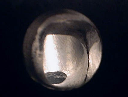
The first head to arrive was Chris Roop's, however it was quickly determined to be cracked! A 2923 model, this is a common crack spot for these heads and in fact, 4/5's or more of the 2923's we've seen are cracked right here.
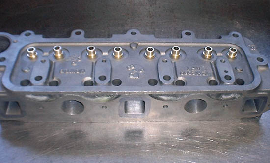
While Chris scrounged around for another head, we received and began work on John Moore's cylinder head. John's head was a 2389 model and definitely in better shape than many that we see. It sported three angle inlet seats, hardened exhaust seat inserts and even though the guides were knurled, they had somewhat decent tolerances. We were relieved to see that the head was in good shape and an excellent candidate for the "Fast Road" job in store for it.
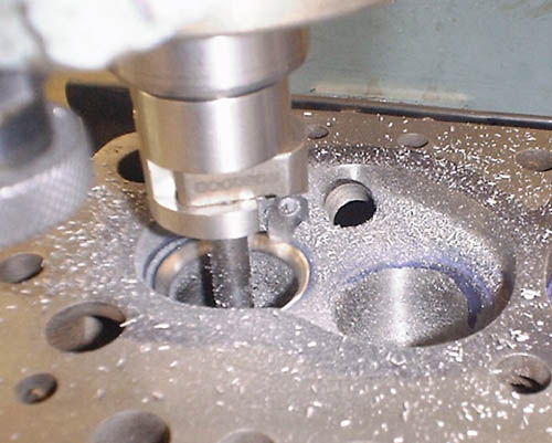
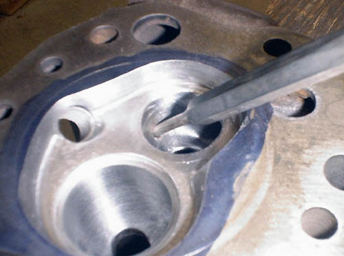
The first job on John Moore's head was to remove the seats as seen above. The TIG welder makes this an easy job, we just weld around them and turn the head upside down to let them fall out!
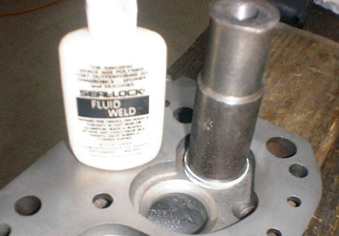
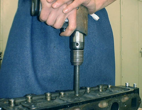
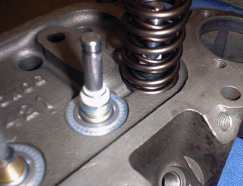
After the old seats were removed, we installed new ones. We use Seal Lock material on all seat installs, we feel it not only helps retain the seats, but also increases thermal conductivity for a longer seat life. The tool above the seat is piloted off the guide and is the driver medium used between the very large hammer and the seat itself during the installation process.
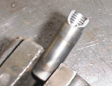
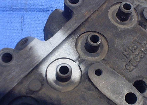
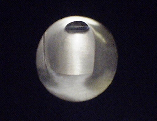
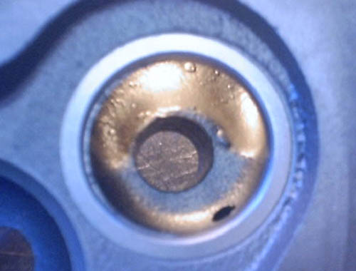
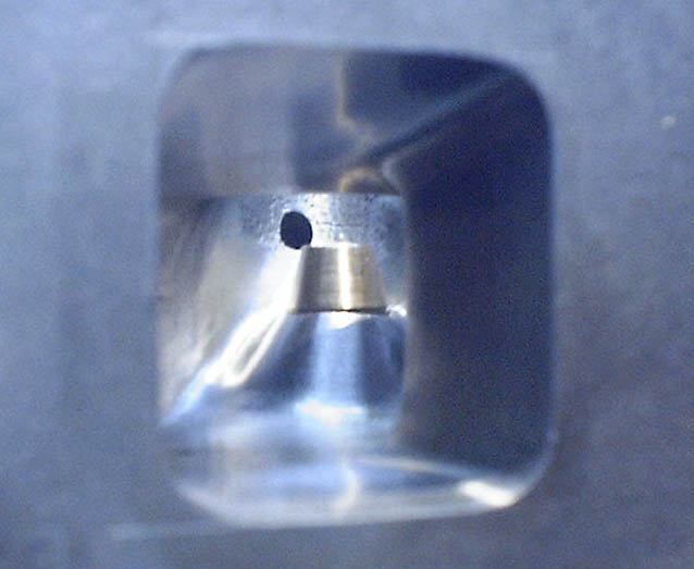
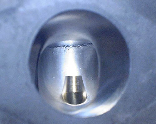
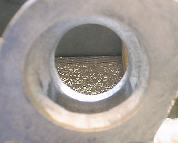
After installing the new hardened seats, the guides can be removed for the port work to be done next. This one happened to break on removal which exposed the knurled interior for an easy camera shot. Knurling is a way of making the inside of the guide smaller, though it is not a favorable way of restoring used guides because the knurled surface will not last very long. Guides are actually cheap and it takes far less time to replace them than to knurl them. This method is generally done only by people who do not have a good source for replacement guides and/or don't know any better.
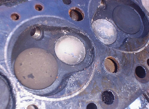
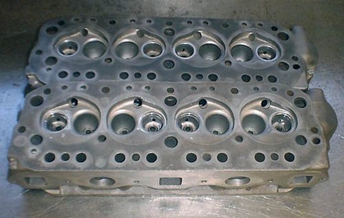
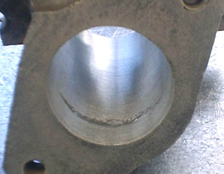
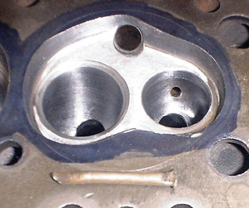
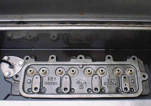
About this time is when Rick Stevens' head showed up and as can be seen, Rick's head had seen better days! The deeply recessed exhaust valves are the first clue that this is a really "high time" cylinder head. Because Rick's head was a 2923, we were very careful to check it over for cracks, our recent experience with Chris Roop's head fresh in our minds.
While we've seen some bad carbon accumulation, this takes the cake, literally! Carbon was caked everywhere on this head. It took a good run-through in the tank with this one to get it ready for bead-blasting and further disassembly.
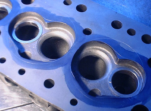
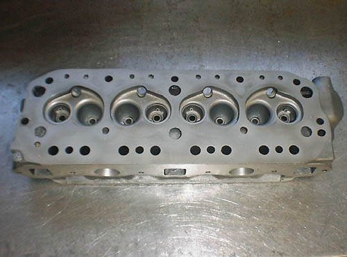
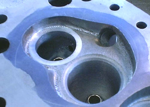
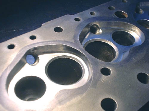
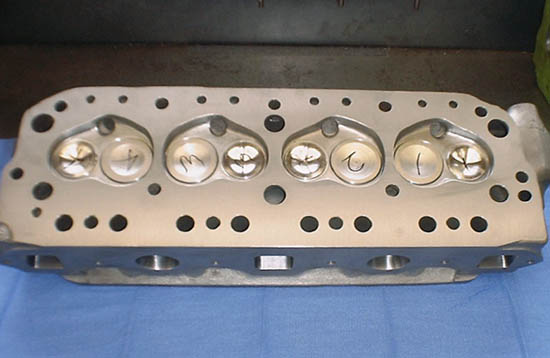
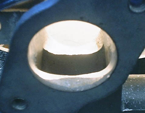
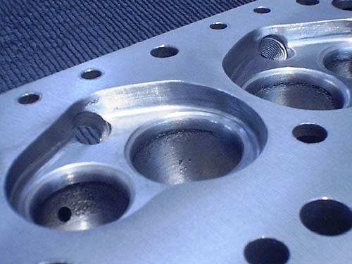
With Rick's head soaking in the gunk tank, we got back to work on John Moore's head, here you can see the deck side laid out for chamber mods. The exhaust guide bosses have already been roughed out in this photo as well. Keen observers will note that the seats are proud of the chamber, this is because the past machinist had used a shallower seat than we do. We will machine these down after the port work is completed and the new guides are installed.
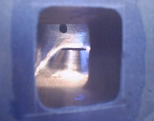
This is a shot of the inlet ports during the process, not as pretty as they'll be later, but taking shape. The port floor and center divider are still partially untouched in this photo (head's upside down).
This is what the final product looks like at night through the light table, and as can be seen, a vast improvement over the last photo.
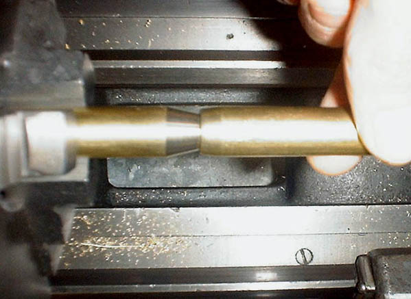
The next step for John's head is to install the new guides, but in order to do that, we first have to prep them. This photo shows a bulleted guide in the lathe and a stock one in my hand, the difference is obvious.
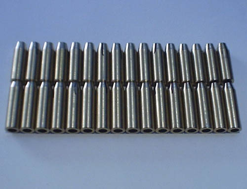
This is what three heads worth of manganese-bronze guides look like, remind anyone of a Rambo movie perhaps?
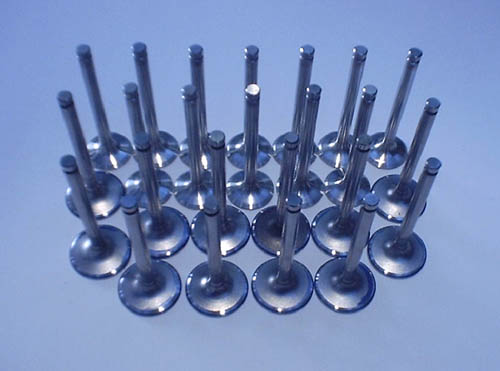
While prepping parts, we also did the valves. We prep the stems, true the seat surfaces, true the circumference and back-cut them, no small task but necessary for the level of work we are doing here.
We grabbed a set of new guides from the photo above and installed them in John's head before topping them for the stem seals we use.
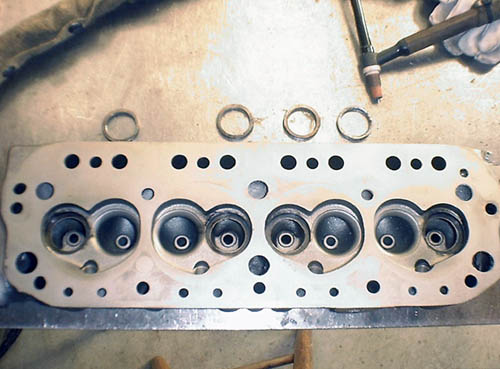
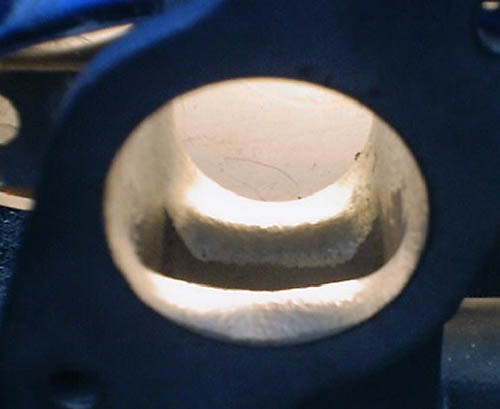
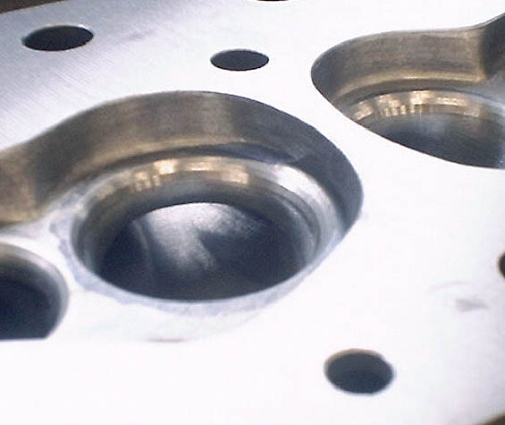
After guide installation, John's exhaust seat inserts were machined down to the level of the chamber, leaving them ready for final polishing. Normally this step is unnecessary as we'll see shortly.
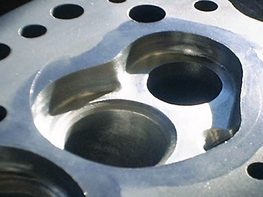
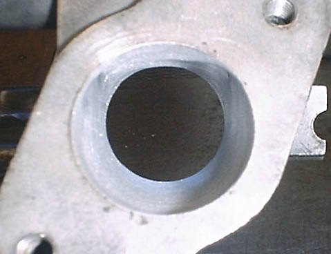
This is John's chamber after grinding it and polishing it smooth, we use an 80 grit finish for both chambers and exhaust ports. This head is about ready for a valve job and final assembly at this point.
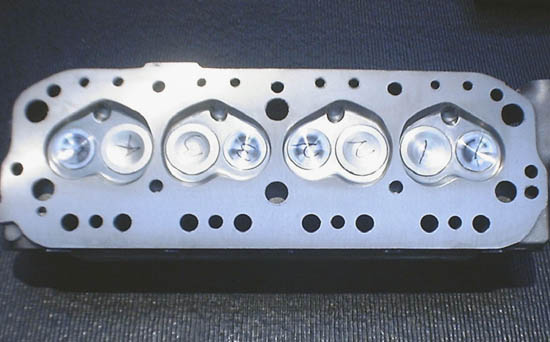
With John Moore's head well in hand, it was time to check up on Rick's head, we also received Chris Roop's replacement in the mean time and cleaned it up as well (both heads are shown here).
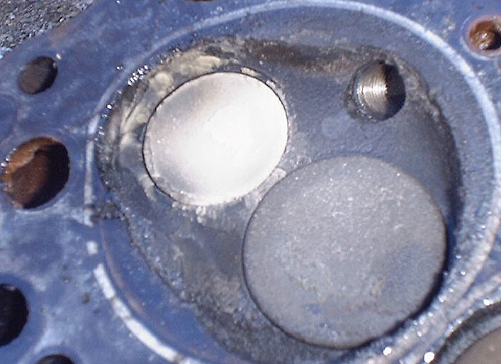
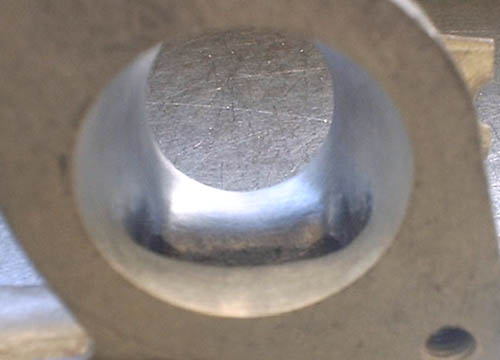
In spite of all the carbon and other assorted gunk, Rick's head cleaned up nicely. Here you can see Rick's new exhaust seats in place, this is how they should look.
Chris Roop's head also received new seats, we used a larger size due to some past work that needed to be removed. Note also the air injector tube still in this head, we will grind this flush and then drive it out.
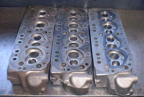
With everyone's head on the table, this is probably as close as these peoples parts will ever be to each other at any given time.
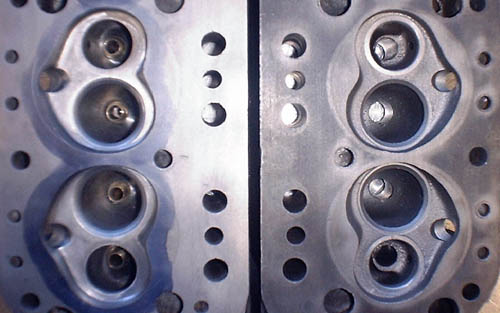
Take a look at both of these heads and note the chamber shapes. I have been accused of making early chambers into later style chambers with my work. I guess it's pretty similar but there are a few differences. I will say, if the material existed for complete shaping of any kind I wanted, all the casting models would look the same coming from me.
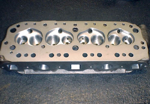
This is a picture of Rick's head after modifying the chambers, a close reference with the above photo should tell the differences from before. We do not modify the later type chambers as radically as we do the earlier type.
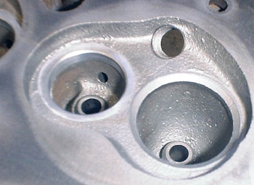
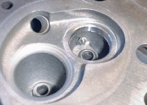
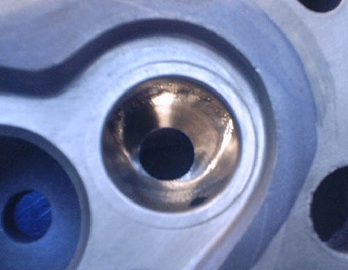
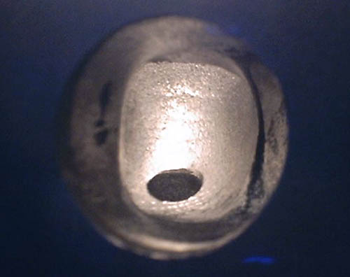
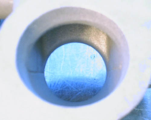
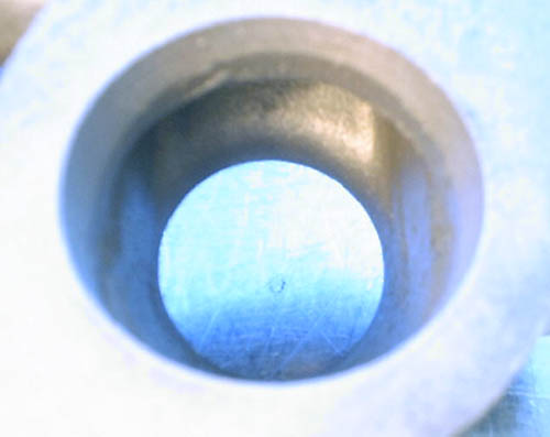
This is one of Rick's exhaust guide bosses before modification, we haven't focused much on the exhaust side of the head yet so let's get into it!
Comparison with the last photo should give everyone the idea as to how much material is removed from the guide bosses on these heads.
If the last photo didn't do it for you, this one should. The stock boss is nearly to the air injector hole and very obstructive.
Possibly not so evident in a photo, 2923 heads have really large bowl areas in their ports right from the factory, making them the sought after head for large valve installations. When I say large, I mean larger than the stock 1.625" valve from the factory. The amount of work necessary to bring the bowl of Rick's head into shape was considerably less than with Moore's or Roop's heads.
One of the disadvantages of a 2923 is this often seen core shift of the inlet and (usually) the exhaust ports. Ideally this undercutting would not exist. We will work very hard on the valve job in this area later, to minimize the effects of this core shift.
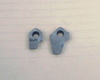
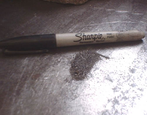
Speaking of seats and seat profiles, one might ask just how this is accomplished these days? Well, good quality seat jobs can still be done with grinding equipment (and we still do this as needed) but the 20th century has brought us machines that can do a much better job. The cutter insert on the left is our custom, full radius exhaust profile with an .058" wide, 45 degree seat. The cutter insert shown on the right is a multi-angle inlet profile having a 35° top angle, a .050" wide 45° seat angle, a 60° undercut, 75° second undercut and an 85° undercut to radius bottom profile. These cutters cost between $30 and $100 depending on whether you buy an off the shelf profile or one custom made to your own specifications.
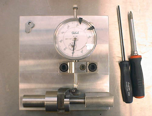
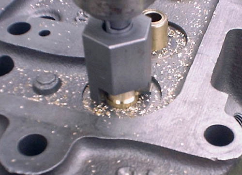
Once the seat profile insert is chosen, we'll install it in the cutting body and then set the correct radius for the valve size in question using the fixture shown above.
With the head bolted on another fixture, we'll bring the axis of the guide in-line with the axis of the spindle, allowing us to easily cut each seat true with each guide. We also have the ability to set each seat level with the deck to within .001"anytime that need arises. This allows us to do a very high quality valve job in about two hours. With grinding equipment, the same level of precision would require at least three times that, and rely heavily on the skill of the operator.
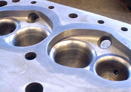
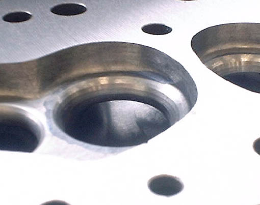
The overall results of the seat cutting process are evident on John Moore's head, as seen above. The inlet seats will be hand blended up to the 60° bottom cut, the exhaust seats need virtually 0 blending by hand because of our custom seat cutter profile.
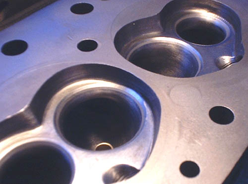
After the blend process, the seat and port areas look like they were made for each other. Because the valve/seat interface is the primary restriction within the engine, this area is extremely critical, not only for mechanical reasons but for flow reasons as well. In our eyes, the porting and valve job specification go hand-in-hand and John should notice a vast improvement in performance with this new valve job.
We surfaced John's head .005" before we gave it the final cleaning and assembly as shown here.
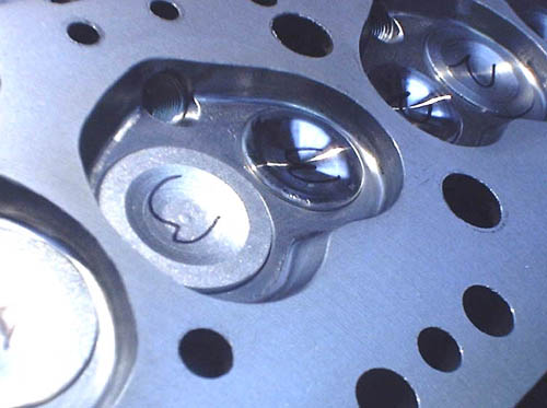
This close-up view shows the relative height of the valves above the chamber surface, good mechanical sealing and airflow will be the results.
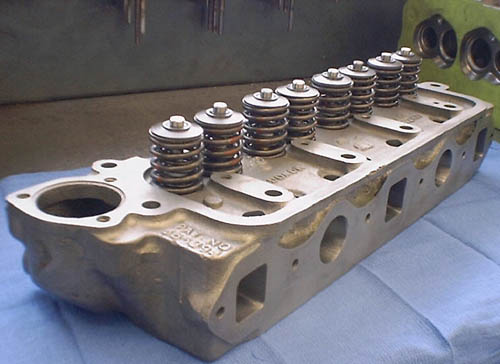
This topside view shows John's head with springs installed and ready to be packed up and shipped. That's Rick's head in the background with tape on the deck, we do that to keep them from getting scratched after surfacing.
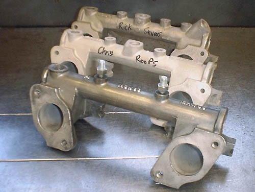
With John's head about ready to be shipped off, it was time to get caught up with the intake manifolds, the group of which can be seen above. These three factory types pretty much sum up what you are likely to see on any given MGB with a stock twin-SU manifold.
Looking in from the carb side, a distinct edge can be seen at the top of the exit side of the manifold on this early example of John Moore's. The abrupt ridge is formed by the balance tube join and is a definite obstruction to airflow through the manifold.
Looking at the later style manifold of Rick Stevens, a more radiused profile can be seen in the same area as above. This more radiused form is better for airflow than is the earlier style sharp edge. If a stock manifold is to be used without modification, this is the preferred type to own. Since we'll be porting all of these examples, the type of manifold in question wont matter, as they will all be essentially the same when we're done.
The first step in porting these manifolds is to smooth the passage as though it were simply a round tube, this is the view from the head flange side. (These manifold sequence photos are inconsistent and not of the highest quality, but hopefully the message will still come through.)
Step two for manifold porting is to flatten off the top of the manifold where the balance tube joins the port itself as seen in this photo. The effect here is that we are going to spread the inefficiency over a larger area, allowing more flow through the manifold with less overall disruption.
With the exit side roughed out, we go to the inlet side and perform a similar sequence of events. The inlet side is not worked as heavily as the exit side because it is shorter and needs to be a good transition to the open area, too much work here will just cause the flow to break away even earlier and that's not what we're after.
With all of the above done, the exit side is given a healthy radius on it's leading edge. See how this form mimics that of the ram tubes often seen on carburetor inlets? Be assured this is no coincidence.
After polishing with 60-grit paper, John's manifold is ready for business.
Getting back to Rick's head, we finished the porting and installed the guides. The same exhaust port as shown earlier in the sequence is seen again here, with obviously more flow area than stock (guide is same length).
Looking in at Rick's inlet ports shows the work done to them. The guides seem to protrude further than they did on John's head because of the increased bowl area of the 2923 casting. The core shift pointed out earlier is still evident in this photo, but much reduced.
I forgot to take a photo of Rick's seats in the semi-finished stage, but this photo shows how they look once blended. The core shift is still there, but no longer a big detriment, we effectively create two different under-seat profiles on the long and short sides to help eliminate the effects of this problem. Simply cutting the seats to the profile used on the long side would cause really poor flow on the short side, our process creates the best compromise of shapes.
Rick's head, ready to be painted and shipped off.
Looking at these close-up photos shows how much higher the exhaust valves sit in the chamber as compared to the way the head was when we got it. When the exhaust valves are sitting down in the chamber, they must lift beyond it's surface before they can even begin to flow. These valves are going to flow as soon as they crack off the seat and that's just what we want to see.
Remember how Rick's later style manifold had a more generous radius than did the earlier types? Once the port is smoothed as a continuous tube, this radius is largely eliminated. The original radius overhung the opening slightly, but we're about to change that as we follow the same sequence we outlined above with John Moore's example.
We decided that if Rick Stevens was a Super-Hero character in a comic book, we'd call him "Captain Core shift." The manifold shown above represents a common area for this to occur. Fortunately the rest of it was off only in ways that made no difference what-so-ever, so it will flow just as well as any other example would (specifically, very well).
One last photo of Rick's manifold ports, this is the same final form as given to the early type manifolds and the results are subsequently, the same.
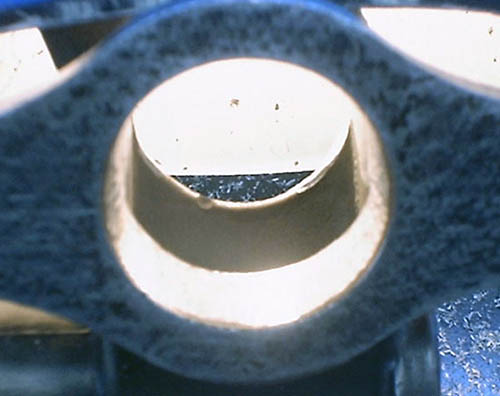
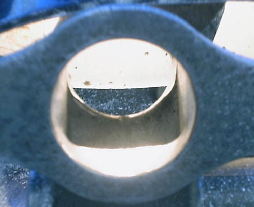
While Rick's head was being done and shipped back, we got to finishing up Chris Roop's head. Since we couldn't get this air injector tube out previously, we cut it off flush with the port and then drove it out afterwards as seen here.
This is the final tube to be removed, the end is crimped over where I grabbed it with vice grips. The head is fully ported and ready for guides at this point.
OK, sorry for the "file photo" to illustrate guide work, but I did not take any photos with these heads. In this photo the guides are actually being removed, but this is also how we install them.
The next step in the process is to cut the seal registers on the top of the guides and this photo shows the tool being used. After this operation we'll ream the guides to size and then proceed with the valve job.
Note the stepped angles of the valve job in this photo. It's hard to tell because of poor picture quality, but there are four distinct angles in this shot. Our next step is to blend the lower cuts out, so as to make a more "friendly" surface for the air to turn against as it tries to exit around the periphery of the valve.
After blending the bottom cuts into the port, only the first 60° angle remains, prior to the 45° seat angle and 35° top cut. Simply blending these bottom cuts out to attain this final profile takes about an hour with a typical fast road head and longer for more sophisticated jobs.
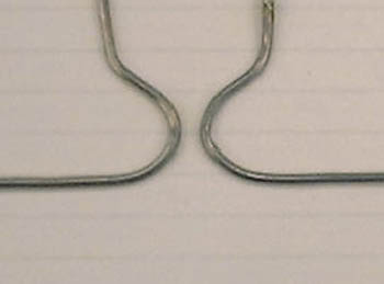
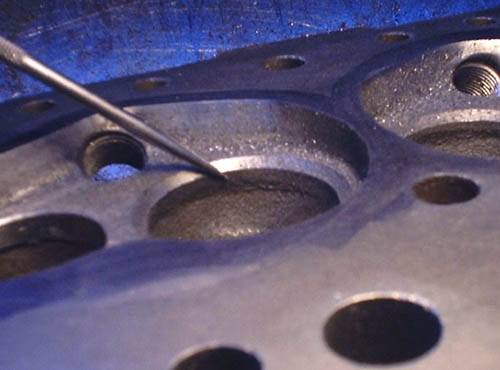
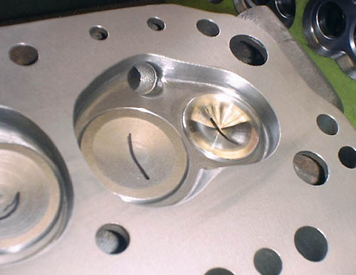
One way to check the profile of hard to see areas like the short side radius of a port, is to bend a piece of solder around it. Seen here are two pieces of solder which have both been bent around the same short side radius of a port. The piece on the left was done after the blending and the piece on the right before (poor picture quality makes it difficult to see the differences between the two).
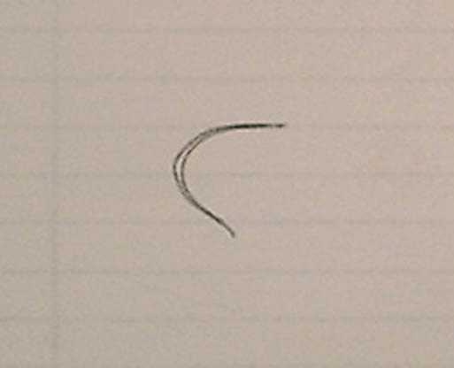
With the trace of each solder profile on a piece of paper, the differences become much more evident (the blended form being the rounder of the two). With a good 40% of the air flowing over the short side radius, this curve into the seat is pretty important (not blending this area correctly can mean a loss of 10 or more CFM on a good head, which is significant).
How much material comes out of one of these heads? Shown here is Chris Roop's head after modification...err, wait...that's the part we didn't use! During the rough-out stage, we use coarse cutters that really throw the chips, the red fibrous stuff is sand paper and cartridge roll fluff.
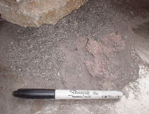
This is all I could sweep up after just doing the seat blend. As already stated, this is one hours worth of work! The seat blend-in is super-critical and time consuming.
After the seat blend, the head is ready for the final cleaning and assembly. I built this tank as a means of cleaning every aspect of the head prior to assembly. That's an air line hooked up to the blanking plate over the thermostat housing, I want to make sure that there is no loose crud or grinding dust anywhere on these heads before they leave. After "boiling" the head via this process for a few minutes, we final rinse the head with clean solvent and then blow it off with high pressure compressed air.
This is a final view of Chris Roop's head after cleaning in the tank and prior to assembly. While I wouldn't recommend it, you could probably eat off it right about now.
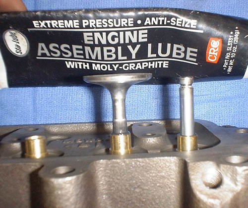
This is the type of assembly lube we prefer for guides, bearings and other similar surfaces. To lube the guides we spread the material on the stem, then install the valve from the top of the guide, pull it out and then install it the right way. This process assures us that there are no dry spots inside the guide which could gall against the stem during start up. Note also the amount of lube we use, just enough is all it takes, you don't need gobs of this stuff running around your engine.
After putting all the valves in their respective guides, we'll put the necessary shims and locators on the head before the Teflon seals. These seals have to be slipped over the valve stem using a protective cover before being pressed on with a special tool. These seals are far more effective than the stock style O-rings and are less prone to failure as well.
Home | Cylinder Heads | Articles
For Sale | Contact
Unless otherwise noted, all material is:
©2005 Sean Brown
All rights reserved.
|