While much has been written about the Lotus/Ford Twin Cam
engine, few will doubt its credibility as a high performance unit. From its
inception at Nurburgring to its long held use in Lotus
road cars, the myriad of race wins and road tests simply speak for
themselves.
While Lotus no doubt produced a capable engine, serious
sports car enthusiasts are always left wanting more. It can be said that to
their eye, a lot of power is good, more is better and too much is just right.
Actually achieving “too much power”
is not an easy task however and this is where many attempted projects fail,
either through poor planning, poor execution, or both. This article will
explore these concepts in detail, show-casing how all too often an attempt at
“too much” gives “not enough”.
This project all started with a conversation I had with Carl Matschke of Big Dreams Auto Restoration in Grants Pass Oregon. Carl was familiar with our work on MG cylinder heads and figured that our expertise
with those types of engines could just as well apply to the Lotus Twin Cam.
Since we both felt Lotus did a pretty good job from the get-go, it was agreed there
was no use spending a lot of money for what may result in a temperamental
engine or one with sub-par road manners. At the conclusion of the conversation,
Carl decided to bring the head by for us to look over and see what (if
anything) might need to be done with it.
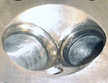
At first glance, some modifications were apparent. The valve
size was definitely not stock and the head was converted from dual Stromberg
carburetors back to Weber DCOE’s. While the Weber manifold
job was done well, the valve size enlargement was questionable. In order to
keep the larger sized valves from hitting each other at overlap, the previous
modifier had obviously sunk the valve seats quite appreciably into the chamber,
leaving a distinct ridge around their periphery. Adding to this were burn
patterns indicating the engine had not been running well and after checking the
actual valve size, I quickly began to feel rather unhappy about the whole thing.
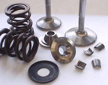
What I found were 1.70” inlet valves and 1.45” exhaust valves
(For reference, stock inlet valve size is 1.53” and the stock exhaust valve
size is 1.32”) and after removing them, I became distressed at the
sight of the poorly executed “big valve” modification. While some attempt at
proper integration of the larger valve seat size was made, my initial reaction
(and that which I still stand by) is that it would have been best had they done
nothing at all. We also found a broken valve spring, but in light of all the
other butchery involved, that was the least of our worries. It was time to call
Carl again and relay the bad news, this head needed help!
In talking with the customer, it was learned that this
engine had previously been modified and tuned by a “Lotus Guru” whose (then)
business was located in the San Francisco Bay Area of California. This man had
been responsible for the larger valves, as well as bigger cams, a .040” overbore,
more compression, and larger than stock 45 DCOE Weber carburetors. With all
these modifications, a dyno output of 130bhp (at the
flywheel) was said to have been obtained. For reference, the early production
versions of the 1558cc engine were factory rated at 105bhp. This knowledge gave
us some clues about what had gone on, as well as some sort of baseline from
which to begin our work.
With both Carl and the customer’s blessings, we embarked on
a mission to better match the cylinder head and induction system components to
the intended use of the engine. Our goals were to get as much torque output
from the engine as we could within a wide and street usable RPM range, make the
engine run on available pump fuel and keep it reliable. Making a statement such
as this would be easy, however actually achieving these goals would take a
little more effort.
Getting Started:
One easy place to start was with the carburetors and inlet
manifold. While the head had been modified to accept a DCOE type manifold, that
manifold had never been modified to accept the larger 45mm sized carburetors. Since
the engine was not making full use of these larger sized carburetors anyway (even
in it’s apparently, highly modified form), we felt a change to a smaller sized
carburetor might be the best remedy.
In fact, sizing the carburetors was an easy choice, as many
charts relating carburetor size to horsepower output are available. Using one
of these charts will show that a pair of 40 DCOE’s
will run out of flow capability (become too small) at about the 150bhp mark. Since
130 horsepower is well within the capabilities of properly tuned 40 DCOE’s, going back to smaller carbs
was an obvious choice. Had we been looking to optimize the engine for higher
RPM horsepower outputs, our choices would have been different. With this simple
choice made, it was time again to tackle the cylinder head.
Our investigation of the cylinder head continued at this
point with some baseline flow testing. We didn't so much care what it flowed at
this point, but were really just curious to see how bad the situation actually
was, and what we found was almost laughable, it was bad!
Airflow evaluation with a project like this is not as simple
as plunking the cylinder head down on the flow bench and sucking some air through
it to “see what it does”. While that might be good enough for some shops, the
actual CFM numbers we record are only the first step in finding out more
information about how well the item under test is conveying air. The simplest
of the three computer programs we use for port evaluation needs only test
depression, CFM and some basic valve and throat size measurements to calculate
a variety of useful outputs. This allows us to view the flow past the valves as
efficiency rather than merely a CFM number. These efficiencies can then be related
to any valve size or cylinder head we’ve ever tested. What might be an
outstanding efficiency level for one make of cylinder head might be very poor
for another, but knowing how one compares to the other in terms of efficiency
gives us an idea of how far we are off from a known “ideal” and a goal to shoot
for. Our initial testing showed the head was achieving very poor efficiency
levels right off the bat and our soon to be cured port molds would help us
understand why.
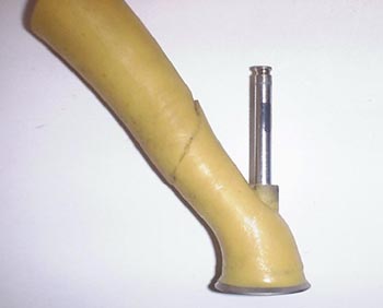
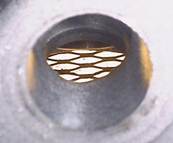
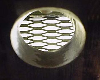
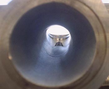
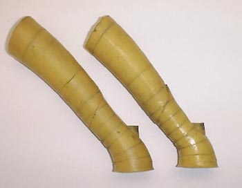
Whenever a head undergoes serious development, we feel it is
absolutely essential to use molds of the ports to evaluate their size and
shape. In the case of the Lotus head, a distinct “hourglass” shape to the inlet
port was immediately evident. This was due to the largely unmodified port
having had a very large inlet valve installed without any consideration to the
transitions from one cross sectional area to the next. While the first half of
the port looked fine (owing to its simple inward tapering shape originally
designed by Lotus) the second half was not so well constructed. The distinct
outward tapering shape of the second half created a port whose over all
dimensions mimicked the form of an ideal venturi, in reverse! This “reverse venturi” shape probably accounted for the inlet ports great
ability to flow air the wrong way and their subsequent poor ability to flow air
the right way (yes we test them both ways). Having a mold like this is of
questionable value when all you intend to do is look at it however and our
intents were to be a little more scientific than that.
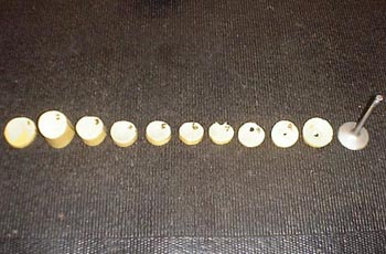
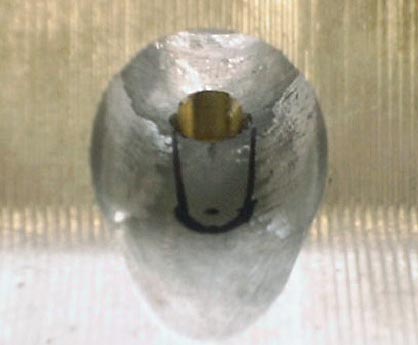
Our next step in the port evaluation process would involve
slicing these molds in critical areas at 90 degree angles to the direction of
airflow. These slices would then be transferred to graph paper and outlined.
The number of squares within the outline of the port mold would indicate the
cross sectional area of that mold slice in square inches. The cross sectional
areas and their distances from the valve seat along the port centerline are
then entered into the computer for further evaluation. Doing this allows us to
evaluate the velocity and efficiency of each segment and help determine where
the port needs to be larger or smaller, by how much and the effect on air
pressure with these changes.
The problem with the larger valves previously installed, was
if the head were ported to match the valve size, the ports would become very
large and poor low range output would be the result. Since we wanted to build
torque at lower RPM’s, we needed to keep the ports
smaller and thus match the valve size more appropriately to these smaller
ports. Since nobody wanted to risk the head to welding it (with subsequent heat
treatment and total re-machining of all critical surfaces), we chose the best
available compromise, a 1.625” inlet valve and a 1.375” exhaust valve. While we would gladly have used
even smaller valves, the previous attempt to “blend in” the seat inserts during
the big valve modification left no material to do the job right and without
welding, what you saw was what you got.
The steps to take in reworking the head were thus:
1) Renew the seat inserts to allow the use of smaller valves
with a better valve job.
2) Modify the port shape to lessen disruptive changes to
port cross sectional area, as well as correct past inconsistencies in port
modification.
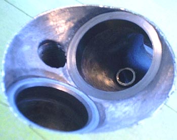
3) Modify the combustion chamber to unshroud the valves at all critical valve lift points and promote greater combustion
efficiency.
4) Perform a high performance valve job allowing maximum
flow past the now smaller valves under the limitations already presented.
Modification:
We removed the seat inserts with a TIG welder before
carefully measuring the seat pockets and ordering inserts of the correct size.
Once the seats had arrived, the head was heated to 200 degrees Fahrenheight while the seats cooled on a block of dry ice.
Doing this allows the head to expand and the seats to contract for ease of
installation and a very secure fit once the temperatures even out.
The next steps would involve hours of delicate port work. Starting
with the exhaust side, the good thing about them was even though they had been
poorly reworked in the past, the head porter had not gone too far by making them
too large. Because we had just enough material left to get the shape we wanted,
we were able to create a very effective exhaust port. Since all the ports were different,
it was a time consuming job using templates and measuring instruments to check
our work. The process was to grind a little and check, then grind some more and
check again, all while being sure not to remove material from areas that were
already made too close by the previous modifier. After the exhaust ports took shape, it was time to move on to the intake side
The inlet manifold did not involve a tremendous amount of
material removal, but still took some time as with the exhaust ports (I.E.
grind and check). The inlet ports inside of the head itself however, were a
bigger challenge. Getting enough cross sectional area past the guide without
creating holes in the roof became the name of the game. In all Lotus Twin Cam
heads, the roof area of the port right before the valve guide dips down a
little. The reason for this seemingly obvious fault is because the inlet cam
gallery and spring platform happen to be right above it. While moving the roof up would allow a
much straighter port, it would also mean breaking into this area up above.
In order to avoid disaster, we used a simple 1:1 thickness checker and
proceeded with caution. To allow us to grind the port to the shape and cross
sectional area we needed right from the start, it was a simple matter of using
our port molds as a guide towards making the necessary templates and measurements for verification.
Further in, the roof was blended as best possible into the
long side of the port with what had been left from the previous modification
work (where we would have filled it in if we could) and the short side was reshaped
using another port mold derived template. All this resulted in a much more even
change in cross sectional area, as well as a port large enough to take full
advantage of the now smaller valve size.
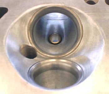
Modifying the chamber was fairly straightforward, as the
previous modifications had not left us with too many options. We settled on a
simple radius profile for deshrouding that would
allow very good low and mid-lift flow without unduly sacrificing upper lift
performance.
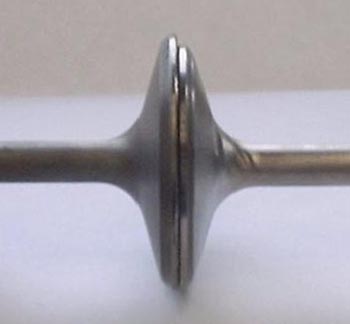
The inlet valve job used very little top cut (due to the
previous work rather than any ideal), a 45 degree seat, a 60 degree first
undercut and a 75 degree second undercut which was then blended into the
throat. The exhaust seat profile was a more complex 7 angle profile using
12-28-45-56-67-78-85 degree steps in that order of occurrence. We then blended
the lower angles into the throat area to simulate a true radius shape.
Back on the flow bench, we found our smaller inlet valves
were now flowing an average 11.4cfm more air at all lifts than had the previous
modifier’s ultra-large combination. The exhaust ports flowed remarkably better as
well, with an average 14.8cfm gain. Since the port sizes had not increased by
much and since the valve sizes had actually been reduced, these gains
represented a dramatic increase in flow efficiency. While we knew the ports
were not as good as they could have been were we given a fresh head to start
with, our flow bench results indicated we had done well and it was time to take
the engine to the dyno to really see just how much of
an effect we had made.
Dyno Time, "Take one"
The first run on the dyno did not
prove as successful as we’d hoped. By the end of the first day we were easily
making high end horsepower, but did not have good low end torque output.
Additionally, the engine was very rough coming up on the cam in the lower RPM
ranges (exactly what we didn’t set out to achieve) and this prompted us to make
some cam timing changes. After making changes in various other areas as well (including
carburetor calibration and ignition timing), we ended up leaving the session with
mixed results.
The good news from our first dyno
session was that our carburetor choice had proved effective. The carbs responded well to every change we made and did not
seem to be a great restriction when viewing manifold vacuum at higher RPM’s. We also made over 150bhp at 6,800 RPM (as high as we
ever took the engine) and the curve had not yet peaked or fallen off. Since we
had reduced both valve size and carburetor size, we felt this 20+ horsepower
increase was very rewarding.
The bad news, was we were going to
need some different cams if our original goals were going to be met. While the upper
RPM power numbers were great (and certainly a far sight better than before) the
torque below 3,800rpm wasn’t good at all and we predicted the engine’s road manners
would be poor as a result. Since high RPM horsepower was not what we set out to
achieve in the first place, a reduction in cam duration was the obvious choice.
After considering various options, a mild competition grind from Iskendarian (with about 12 degrees less duration and
only slightly less valve lift) was chosen. Our initial inlet cam setting was on
a 102 degree inlet center line with a 104 degree separation.
Dyno Time, "Take two"
Our second trip to the dyno proved
much more satisfying. Immediately our baseline pulls established over 15ft/lbs more
torque at 3,500 RPM than we’d had previously. After spending time narrowing in
on an ideal carburetor calibration and timing advance setting, we had increased
that gap to over 20ft/lbs and the rough running we had experienced previously
was nearly imperceptible. After lunch I opted to try some cam timing variations
and gained even more low RPM torque at nearly no loss in upper RPM horsepower.
The final runs showed a 32ft/lbs gain in torque over the previous cams and we
had only lost about 10bhp at the very upper RPM ranges. In fact the Isky cams had proven to be much more effective from the
beginning of our pulls all the way up around 5,300rpm where they began to lose
out to the original speed grind installed by the previous mechanic.
Summation:
By utilizing smaller valves, smaller cams and smaller
carburetors, we gained 12bhp and untold amounts of torque (the original dyno results were unfortunately not available). Reasons for
this are as follows:
- By
using smaller valves and porting the cylinder head to match their size as
best possible, we were able to provide the engine with the airflow
potential it needed to make excellent torque and horsepower.
- By
using smaller carburetors we allowed them to function as designed for
better atomization capabilities and proper metering.
- By
using smaller cams, we were able to “pivot” the torque curve around the
peak torque point to emphasize the lower RPM ranges we originally
targeted. Additionally, the early inlet closing point encouraged full use
of the (now lower) 10.4:1 compression ratio, while still allowing safe
running with available pump fuel.
By now it should be obvious that good engine packages don’t
just happen by accident, they come about through careful
consideration of all the components and to their interactions together as a system. Without flowbench and dyno testing, this project could never have turned out as successfully as it did. Knowledge of the right items to use and thorough testing to verify that all components were working in harmony was essential and necessary.
With everything said and done, we were very pleased with the
increase in performance and the customer expressed great appreciation that we were
able to spend the amount of time and effort we did with development and testing
to ensure that the job was done right. While this article has only touched on the most notable points of the project, juggling the many details involved was no easy task. As with any project of it's kind, this job will only serve to build experience and become the baseline for future developments. If the results we attained this time are any indication, we'll be looking forward to the future!